Expert en condensateurs électroniques de torche
Blogues
Maison

Blogues

  • CIOE 2026 Is Coming | A Quick Guide to Tianji Technology’s High-Speed Optical Communication Product Portfolio
    Sep 07, 2026
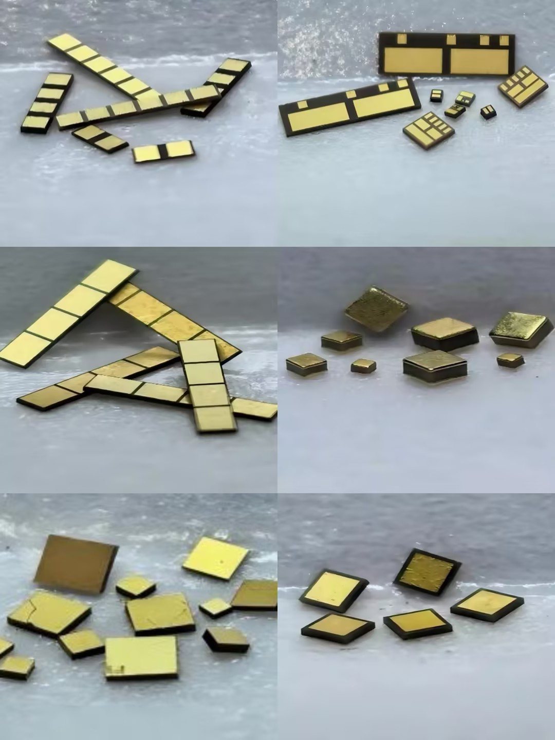
      I. Introduction   As data centers, AI clusters, 5G transport networks, metro networks, and coherent communication systems evolve toward 400G, 800G, and even 1.6T and 3.2T transmission rates, the challenges associated with electrical interconnection, optoelectronic conversion, and thermal management inside optical modules continue to increase.   Traditional optical modules have primarily focused on key active components such as lasers, photodetectors, TIAs, driver ICs, and DSPs. However, as optical modules move toward higher speeds, smaller form factors, and greater reliability, the importance of passive components and packaging materials is also increasing.   Among them, SLCCs (Single Layer Ceramic Capacitors), silicon capacitors, and ceramic heat sinks play important roles in high-frequency signal coupling, local decoupling, heat spreading, temperature stabilization, and reliability assurance. They have become essential components in the design and packaging of high-end optical modules.   To address these requirements, Tianji Technology has established a product portfolio covering SLCCs, silicon capacitors, ceramic thin-film circuits (ceramic heat sinks), and passive integrated devices. Its SLCC products are manufactured through a fully in-house and independently controlled process, while its silicon capacitors are capable of volume production. For thin-film circuits, available substrate materials include alumina, aluminum nitride, silicon carbide, diamond, fused quartz (SiO₂), and high-borosilicate glass. The company also offers a broad range of processing capabilities, including fine-line patterning, drilling, copper via filling, sidewall metallization, sidewall patterning, tantalum nitride resistors, preformed AuSn solder pads, PI solder mask, thick/thin gold metallization, and DPC processes.   An optical module is essentially a highly integrated optoelectronic conversion system. The transmitter side typically includes a laser, laser driver, modulator, monitoring photodetector, automatic power control circuitry, and temperature-control structures. The receiver side typically includes a photodetector, transimpedance amplifier, limiting amplifier, or CDR circuitry. High-speed modules may also integrate DSPs, SerDes, power-management ICs, and multiple high-speed differential signal lines.   As channel counts increase, transmission rates rise, and available packaging space becomes more constrained, the selection of capacitors and heat sinks can directly affect eye-diagram quality, jitter, bit error rate, optical power stability, and long-term service life.   This article focuses on these three key component categories, covering their technical principles, application scenarios, selection considerations, and development trends, with the aim of providing a reference for optical module design, component selection, and market development.   (Figure 1. Schematic Diagram of an Optical Module)         II. Applications of SLCCs in Optical Modules   2.1 Overview of SLCC Technical Characteristics   SLCC (Single Layer Ceramic Capacitor) refers to a single-layer ceramic capacitor. Compared with multilayer ceramic capacitors (MLCCs), SLCCs have a simpler structure, consisting of only a single dielectric layer with electrodes on the top and bottom surfaces. As a result, they feature lower parasitic inductance (ESL) and equivalent series resistance (ESR), higher self-resonant frequencies, and better high-frequency performance. SLCCs are primarily used at frequencies above 3 GHz and can operate at frequencies up to 100 GHz, making them suitable for RF, microwave, millimeter-wave, and high-speed digital signal environments.   SLCCs and MLCCs differ significantly in structure, electrical performance, and mounting methods, and each is suited to different application scenarios and assembly processes. SLCCs are designed for micro-assembly processes and are typically mounted using gold wire or gold ribbon bonding. They are not suitable for conventional surface-mount assembly. In contrast, MLCCs are designed for surface-mount technology (SMT) and are typically soldered onto the PCB.   In optical modules, SLCCs are generally not used for bulk energy storage. Instead, they are primarily used for high-frequency coupling, bypassing, impedance matching, filtering, and local compensation, serving more as precision high-frequency tuning components within the circuit.         (Figure 2. SLCC / Thin-Film Capacitor Product Forms for Micro-Assembly Inside Optical Devices)     2.2 Typical Applications of SLCCs in Optical Modules   (1) High-Frequency Bypass in Laser Driver Links: SLCCs can be used as high-frequency bypass capacitors near laser drivers, EML driver stages, modulation bias networks, or high-speed signal paths to reduce high-frequency noise, improve power integrity, and suppress parasitic oscillation.   High-speed laser drive currents have fast signal edges, and parasitic inductance in the package and interconnects can easily cause overshoot, ringing, and power-supply disturbances. Due to their small size, low ESL, and fast response, SLCCs can provide an effective bypass path at high frequencies.         (Figure 3. Schematic of the AlN Substrate, Capacitor, and High-Speed Electrode Areas in an EML Package)   (2) Local Decoupling and Filtering at the Optical Receiver: SLCCs can be used for local decoupling, bias filtering, or high-frequency compensation near the TIA to reduce high-frequency noise coupling. Signals at the receiver are typically very small, and the TIA input is highly sensitive to noise. Power-supply noise, ground bounce, and parasitic coupling can therefore affect receiver sensitivity. Placing SLCCs close to sensitive nodes can help improve the stability of the receiver circuit.   (Figure 4. Schematic of the PIN PD, TIA, Capacitors, and Gold-Wire Interconnections Inside a ROSA)     (3) Integration Inside TO Packages / TOSA / ROSA / BOSA: For optical devices using gold-wire bonding, ceramic carriers, thin-film circuits, or hybrid integrated packaging, SLCCs can be integrated directly into the optical device through AuSn soldering, conductive adhesive, or gold-wire interconnection, enabling compact high-frequency passive networks.   The main advantages of SLCCs are their good high-frequency performance, mature manufacturing process, and high reliability. However, their capacitance is generally relatively small, typically ranging from 0.05 pF to 10,000 pF, with values below 1,000 pF being the most commonly used. Therefore, SLCCs are not suitable for bulk energy-storage applications.     2.3 Common Tianji Technology SLCC Specifications for Optical Communication   The table below lists commonly used Tianji Technology SLCC part numbers and specification ranges for optical communication applications, covering multiple sizes from Type 10 (0.25 mm) to Type 30 (0.76 mm). Available voltage ratings include 10 V, 25 V, and 50 V, meeting different requirements for packaging space and high-frequency performance.     (Common Tianji Technology SLCC Specifications for Optical Communication Applications)   III. Applications of Silicon Capacitors in Optical Modules   3.1 Overview of Silicon Capacitor Technical Characteristics   Silicon capacitors are high-performance capacitors fabricated on silicon substrates using semiconductor processes, thin-film technologies, or deep-trench structures. Compared with conventional MLCCs, silicon capacitors offer advantages such as smaller size, thinner profiles, low parasitic parameters, good consistency, high temperature stability, and suitability for high-frequency and broadband applications. They are particularly well suited to applications with stringent requirements for size, parasitic parameters, and high-frequency performance.   For example, silicon capacitors can be fabricated with a thickness of less than 100 μm, while ESL can be below 0.05 nH, and the temperature coefficient of capacitance can be maintained at a relatively low level. As high-speed optical modules continue to move toward higher density, greater bandwidth, and smaller package sizes, demand for silicon capacitors in 400G, 800G, and 1.6T optical modules, as well as silicon photonics modules, is gradually increasing.   Another major advantage of silicon capacitors is their good compatibility with silicon-based manufacturing processes. Silicon photonics modules typically integrate modulators, photodetectors, waveguides, couplers, and other devices on a silicon-based platform. Silicon capacitors can therefore be more readily integrated close to the chip, within IPDs, or on interposers. This is important for reducing parasitic parameters, shortening interconnect paths, and increasing bandwidth.     (Figure 5. Schematic of 2D and 3D Silicon Capacitor Structures)     3.2 Three Core Applications of Silicon Capacitors in Optical Modules   (1) AC Coupling for High-Speed Signals: High-speed SerDes, DSPs, drivers, and TIAs often operate at different DC bias points, making AC coupling capacitors necessary for transmitting high-speed differential signals. At high frequencies, conventional MLCCs may be affected by parasitic inductance, dielectric loss, and package size, which can degrade insertion loss, return loss, and phase consistency.   With their low parasitic inductance and highly consistent structure, silicon capacitors are better suited to ultra-wideband high-speed signal paths, particularly for PAM4 links and high-density channel layouts. In 400G QSFP-DD DR4 optical modules, AC coupling capacitors are typically used in high-speed electrical links for DC blocking and AC coupling.   (2) Power Decoupling and Local Bypass: DSPs, laser drivers, TIAs, CDRs, and power-management ICs inside optical modules are highly sensitive to power-supply noise. Silicon capacitors can be placed close to chip power pins, laser-driver power terminals, or TIA supply nodes to provide high-frequency decoupling.   For highly space-constrained platforms such as QSFP-DD, OSFP, CPO, and silicon photonics packages, the small footprint and low profile of silicon capacitors help increase layout density, shorten current return paths, and improve power integrity.   (3) On-Chip or Near-Chip Integration in Silicon Photonics and Co-Packaged Optics (CPO): Silicon photonics modules typically integrate modulators, photodetectors, waveguides, couplers, and other devices on a silicon-based platform, while also requiring high-density interconnection with driver ICs, TIAs, and DSPs.   Because silicon capacitors are highly compatible with silicon-based processes, they can be more readily integrated close to the chip, within IPDs, or on interposers. This is important for reducing parasitic parameters, shortening interconnect paths, and increasing bandwidth.   However, silicon capacitors are not mandatory for every optical module design. For lower-speed and cost-sensitive modules, MLCCs and SLCCs may still provide better overall cost-effectiveness in some applications. Silicon capacitors are more suitable for high-end optical modules, high-speed optical engines, silicon photonics platforms, co-packaged optics (CPO), and applications with extremely demanding requirements for space, frequency response, and parasitic performance.   (Figure 6. Schematic of High-Speed Electrical Links, Optical Devices, and Local Passive Components in an Optical Module)     3.3 Common Tianji Technology Silicon Capacitor Specifications for Optical Communication   Tianji Technology’s silicon capacitor products can be divided into two main categories: vertical-electrode silicon capacitors and coplanar-electrode silicon capacitors.   Common Part Numbers and Specification Ranges of Tianji Technology Vertical-Electrode Silicon Capacitors   (Common Part Numbers and Specification Ranges of Tianji Technology Vertical-Electrode Silicon Capacitors)       (Common Part Numbers and Specification Ranges of Tianji Technology Coplanar-Electrode Silicon Capacitors)   IV. Applications of Ceramic Heat Sinks in Optical Modules   4.1 Functions and Application Scenarios of Ceramic Heat Sinks   Ceramic heat sinks are typically positioned between the optical chip and the metal package, TEC, package substrate, or module base, where they provide multiple functions including heat spreading, mechanical support, stress buffering, and electrical insulation.   On the transmitter side, ceramic heat sinks help control the junction temperature of lasers such as CW-DFB, EML, and VCSEL devices, helping suppress wavelength drift, increases in threshold current, and reductions in service life. On the receiver side, they can serve as submounts or ceramic carriers for PIN, APD, Ge, and coherent photodetectors, while conducting heat generated by the detector and nearby TIA to help reduce dark current, noise, and optical coupling drift.   The thermal-management priorities of these two types of devices differ. Lasers generally generate more heat, so the primary focus is on reducing thermal resistance and maintaining temperature uniformity. Conventional photodetectors generate less heat and place greater emphasis on low parasitic effects, electrical insulation, and optical alignment stability. However, localized hot spots may still occur in applications involving high-power photodetectors, nearby TIAs, or silicon photonics heaters.   Therefore, ceramic heat sinks should be designed in coordination with chip power dissipation, solder layers, interfacial thermal resistance, signal routing, and the heat-dissipation path through the package.   4.2 Material Selection for AlN and SiC Ceramic Heat Sinks   According to the material property comparison table, aluminum nitride (AlN) has a thermal conductivity of at least 170 W/m·K and a coefficient of thermal expansion of approximately 4.6 × 10⁻⁶/K.   For silicon carbide (SiC), thermal conductivity is at least 350 W/m·K along the C-axis and at least 390 W/m·K along the A-axis, while its coefficient of thermal expansion is approximately 4.0–4.5 × 10⁻⁶/K.   Both materials offer good thermal-expansion compatibility with semiconductor chips. SiC provides greater advantages in applications involving localized hot-spot spreading and high heat-flux densities.   (Figure 7. Comparison of Substrate Material Properties for Thin-Film Circuits)           AlN offers good electrical insulation, with a dielectric constant of approximately 8.6, making it well suited for the fabrication of thin-film circuits, high-speed electrodes, and gold-wire bonding areas. It is a mature choice for EML, PIN/APD, and conventional ROSA submounts.   SiC provides higher thermal conductivity and greater stiffness, making it more suitable for high-power CW lasers, multi-channel arrays, and silicon photonics or coherent receiver applications with concentrated hot spots. Its use should also be evaluated in combination with electrode isolation, metallization processes, and overall cost.   4.3 Heat Dissipation Performance and Temperature Effects   Results reported in the Chinese Journal of Lasers for devices using the same package structure showed that the total thermal resistance of two devices with SiC transition heat sinks was approximately 3.00 °C/W and 3.05 °C/W, compared with approximately 3.40 °C/W and 3.48 °C/W for two devices using AlN heat sinks. Under the packaging and test conditions used in the study, the average thermal resistance of the SiC devices was approximately 14.7% lower.   At a continuous current of 16 A, a representative SiC-based device achieved an output power of 15.9 W and an electro-optical conversion efficiency of 56.8%, compared with 15.0 W and 53.2% for the AlN-based device.   Under the specific package structure and test conditions adopted in this study, SiC heat sinks demonstrated lower total thermal resistance and better performance under high thermal loads.   (Figure 8. Measured Temperature and Thermal Resistance Curves of Lasers Packaged with SiC and AlN Heat Sinks)   The temperature rise on the photodetector side should not be overlooked either. A 2024 study published in IEEE Photonics Journal on high-power MUTC InGaAs photodetectors showed that when the dissipated power increased from several tens of milliwatts to approximately 600 mW, the temperature at the n-contact rose from around 300 K to nearly 500 K. The trends obtained from the numerical model, finite-element simulation, and experimental results were consistent.   Although this operating condition is not equivalent to that of a conventional low-power ROSA, the results demonstrate that high optical power, high bias conditions, or nearby heat sources can significantly increase photodetector temperature.     (Figure 9. InGaAs Photodetector Contact Temperature as a Function of Dissipated Power)   The absolute temperature of the heat sink also depends on factors such as chip power dissipation, heat-sink dimensions, solder layers, interfacial thermal resistance, and base temperature. When comparing AlN and SiC, the same package structure and boundary conditions must be used. Temperature results obtained from one specific configuration should not be directly applied to all laser or photodetector packages.   4.4 Laser and Photodetector Packaging Examples   In high-speed EML packages, AlN submounts simultaneously provide heat spreading, mechanical support, electrode mounting, and gold-wire interconnection. In ROSA assemblies, metallized ceramic submounts are used to secure the photodetector, conduct heat away from the device, and route high-speed electrical signals.   The two publicly available product images below illustrate typical applications of ceramic heat sinks on the laser side and photodetector side, respectively.   (Figure 10. EML Laser Bonded on an AlN Submount) (Figure 11. InGaAs Photodiode Mounted on a Metallized Ceramic Submount)     V. Synergy Among the Three Types of Components in Optical Modules   Although SLCCs, silicon capacitors, and ceramic heat sinks belong to different categories of fundamental components and materials, they perform complementary roles in high-speed optical modules, supporting both high-speed electrical performance optimization and thermal management through coordinated package design. SLCCs and silicon capacitors primarily address high-speed electrical signal integrity and power integrity, while ceramic heat sinks mainly support the temperature stability and reliability of optical devices.   In high-speed optical modules, electrical and thermal performance are closely interconnected. Rising temperatures can shift the operating points of lasers and photodetectors and can also affect circuit noise and high-speed signal quality. Conversely, power-supply noise and high-frequency ringing may distort laser modulation waveforms, further degrading optical signal quality.   On the transmitter side, the laser driver, SLCCs, silicon capacitors, and laser heat sink work together to determine whether the laser can deliver stable high-speed optical signals. SLCCs and silicon capacitors help provide clean high-frequency power and stable signal coupling, while the heat sink controls laser-chip temperature and wavelength drift. This coordinated electrical and thermal design becomes even more important for high-speed EMLs and external lasers used in silicon photonics systems.   On the receiver side, the photodetector heat sink, silicon capacitors, SLCCs, and TIA collectively influence receiver sensitivity. The photodetector heat sink helps reduce temperature drift and noise, while silicon capacitors and SLCCs improve the high-frequency characteristics of the TIA power supply and high-speed output path. In high-speed PAM4 receiver links, power-supply noise, parasitic inductance, temperature drift, or package discontinuities can all reduce eye opening and increase the bit error rate.   At the overall optical-module system level, the coordination among these three types of components also directly affects the maximum data rate and long-term reliability that the module can support. When SLCCs and silicon capacitors are used to optimize high-speed electrical performance, the package layout can also be designed to minimize impediments to heat flow. Working together with ceramic heat sinks, heat generated by optical and electronic chips can be efficiently transferred away, preventing localized temperature rise from further degrading electrical performance.   At the same time, stable electrical performance can reduce unnecessary power dissipation and heat generation, thereby easing the thermal load on the heat sink. This creates a positive interaction between electrical and thermal performance, ultimately enabling the optical module to operate at high speed with greater stability and reliability.   (Figure 12. Schematic Diagram of an Optical Module Structure)   VI. Development Trends   In the future, optical modules will continue to evolve toward higher data rates, smaller form factors, lower power consumption, and greater integration. 400G and 800G have already become mainstream in data centers, while high-end systems are continuing to advance toward 1.6T, 3.2T, and co-packaged optics (CPO). Along with this trend, SLCCs, silicon capacitors, and heat-sink materials will also continue to evolve.   First, capacitors will move from board-level discrete components toward near-chip integration. Silicon capacitors, miniaturized SLCCs, and thin-film passive devices will increasingly be integrated inside optical engines to shorten interconnect paths, reduce parasitic parameters, and increase bandwidth.   Second, heat-sink materials will evolve from conventional ceramics and metal composites toward materials with higher thermal conductivity. AlN will remain one of the mainstream choices, while demand for materials such as SiC, CuW, and CVD diamond is also expected to increase further in high-power-density and high-reliability applications.   Third, optical module design will shift from optimizing individual components toward integrated electrical, thermal, optical, and mechanical co-design. High-speed signal integrity, power integrity, heat-spreading paths, optical coupling stability, and package stress must all be considered together. Capacitors and heat sinks are no longer merely supporting components; they are becoming important factors that influence the performance limits of the module.   Fourth, as the domestic supply chain for high-speed optical modules, silicon photonics platforms, and high-speed optical engines continues to develop, higher requirements are being placed on the performance, delivery capability, and supply-chain assurance of high-performance SLCCs, silicon capacitors, AlN heat sinks, SiC heat sinks, thin-film circuits, and related packaging materials. This also creates new opportunities for domestic manufacturers of high-performance passive components and advanced packaging materials. VII. Conclusion   In high-speed optical modules, although SLCCs, silicon capacitors, and ceramic heat sinks are not core active devices such as DSPs, lasers, and photodetectors, their performance and proper application have an important impact on signal integrity, temperature stability, receiver performance, and long-term reliability.   Among them, SLCCs are mainly used for high-frequency bypassing, coupling, impedance compensation, and related applications;   Silicon capacitors can be used in high-speed broadband links, miniaturized decoupling, and near-chip integration in silicon photonics;   Ceramic heat sinks provide heat spreading, mechanical support, and temperature stabilization in the packaging of optical devices and photodetectors.   As optical modules advance beyond 400G and 800G toward 1.6T, silicon photonics, coherent optical communication, and CPO, the importance of high-frequency passive components, high-thermal-conductivity ceramic materials, thin-film circuits, and advanced packaging processes will continue to increase. These technologies are becoming important factors in determining the upper performance limits of optical systems.   Future competition in optical modules will therefore not only center on lasers, DSPs, and silicon photonics chips, but also on capabilities in high-frequency passive components, advanced heat-sink materials, thin-film circuits, and integrated packaging design.   For high-speed optical communication applications, Tianji Technology continues to expand its product portfolio and manufacturing capabilities in SLCCs, silicon capacitors, ceramic thin-film circuits, and high-thermal-conductivity ceramic materials. In addition to its existing facilities, the company is constructing a new manufacturing site with a building area of more than 40,000 m². Additional production capacity is expected to be released progressively from 2027, further strengthening its volume manufacturing and delivery capabilities and providing high-frequency passive components, thin-film circuits, and advanced packaging support for high-speed optical modules and optical engines.  
    EN SAVOIR PLUS
  • Why Do MLCCs Crack, and How Can Flexible Termination Help?
    Aug 07, 2026
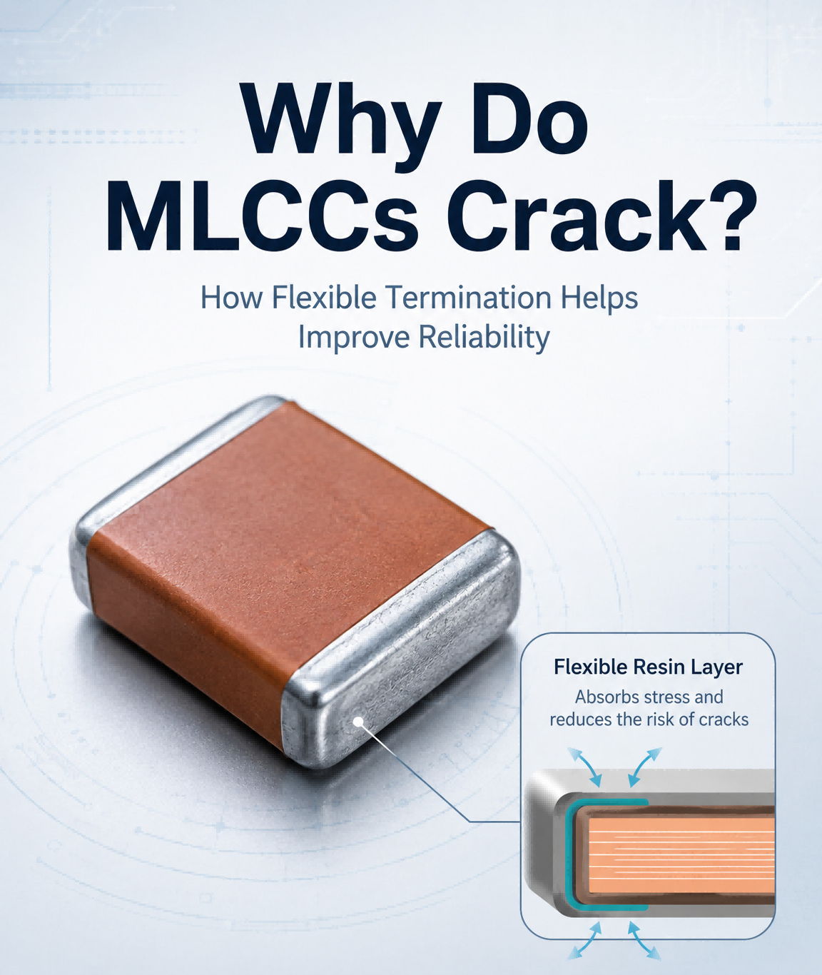
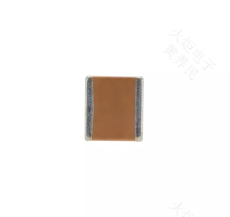
    Why Do MLCCs Crack, and How Can Flexible Termination Help?   MLCCs are widely used in modern electronic systems because of their compact size, stable electrical performance, and high reliability. However, ceramic materials are inherently brittle, which means excessive mechanical stress can create cracks and potentially affect long-term circuit reliability.   Why Do MLCC Cracks Occur?   Mechanical stress can be introduced during PCB assembly, soldering, board depaneling, mounting, or even during normal operation when the PCB bends or expands under temperature changes. Because a conventional MLCC has relatively rigid terminations, external stress transferred from the PCB may reach the ceramic body directly. In demanding applications, repeated bending or thermal-mechanical stress can increase the risk of internal cracking.     How Does Flexible Termination Technology Help?   Flexible termination MLCCs introduce an additional resin electrode layer at the end termination. This flexible layer helps absorb external mechanical stress before it reaches the ceramic body, reducing the possibility of crack formation. This structure is especially useful in circuits where resistance to PCB bending is important, such as switching power supplies, telecommunication base stations, industrial electronics, and other high-reliability systems.   Torch Electron Flexible Termination MLCC Solutions       Torch Electron offers Flexible Termination Chip Multilayer Ceramic Capacitors with CG, 2R1, and 2C1 dielectric options. Key product capabilities include: Rated voltage: 25V to 500V Package sizes: 0402 to 1210 Operating temperature: -55°C to +125°C Flexible resin electrode structure for improved resistance to external stress Different series can support applications such as high-frequency coupling, resonance circuits, filtering, bypassing, low-noise circuits, and switching power supplies.   By combining flexible termination technology with reliable ceramic capacitor manufacturing, Torch Electron provides MLCC solutions designed to improve mechanical durability while maintaining stable electrical performance.
    EN SAVOIR PLUS
  • How to Choose the Right SMD MLCC for Your Electronic Design
    Aug 05, 2026
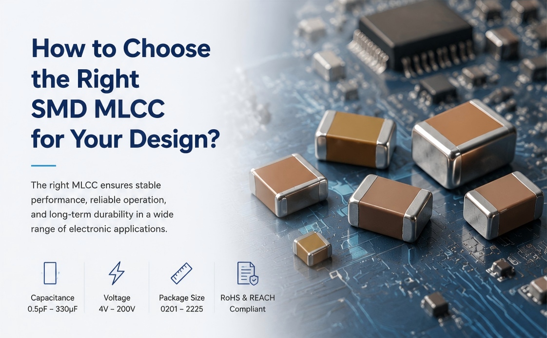
    How to Choose the Right SMD MLCC for Your Electronic Design?   Selecting the right SMD Multilayer Ceramic Chip Capacitor (MLCC) is more important than ever as electronic devices continue to become smaller, faster, and more integrated. Whether you're designing consumer electronics, industrial equipment, or medical devices, choosing the appropriate MLCC can significantly improve circuit reliability and overall system performance.     What Should You Consider When Choosing an SMD MLCC?   A suitable MLCC is not determined by capacitance alone. Engineers should evaluate several key factors, including rated voltage, dielectric material, package size, operating temperature, and application requirements.   For example, C0G dielectric offers excellent stability and low loss for precision circuits, while X7R and X5R provide higher capacitance values for general-purpose and space-constrained designs. Selecting the right package size—from 0201 to 2225—also helps optimize PCB layout and product miniaturization.     Torch Electron SMD MLCC Solutions   Torch Electron offers a comprehensive portfolio of SMD Multilayer Ceramic Chip Capacitors to support a wide range of electronic applications.   Our SMD MLCC solutions feature:   Capacitance: 0.5pF to 330μF Rated Voltage: 4V to 200V Package Sizes: 0201 to 2225 Dielectric Options: C0G, X7R, and X5R Lead-free terminations compliant with RoHS and REACH   Designed for stable electrical performance and high reliability, Torch Electron SMD MLCCs are widely used in consumer electronics, industrial control, railway transit, and medical equipment, helping customers meet both performance and reliability requirements.   A Reliable Partner for Your MLCC Needs   Choosing the right MLCC is essential to achieving reliable circuit performance. Backed by years of ceramic capacitor manufacturing experience, advanced production technology, and strict quality management, Torch Electron is committed to providing dependable SMD MLCC solutions for customers worldwide.
    EN SAVOIR PLUS
  • What Makes High Voltage MLCCs a Reliable Solution for Advanced Applications?
    Aug 03, 2026
    Meeting the Growing Demand for High Voltage Capacitor Solutions   With the continuous development of power electronics, industrial systems, and advanced electronic equipment, capacitors are required to deliver higher voltage endurance, stable performance, and long-term reliability. High Voltage Multilayer Ceramic Chip Capacitors (High Voltage MLCCs) are designed to meet these demanding requirements by providing excellent electrical performance in high-voltage applications.   Compared with standard MLCCs, High Voltage MLCCs are specially designed to withstand higher operating voltages while maintaining reliable capacitance characteristics and stable performance under challenging conditions.   Torch Electron High Voltage MLCC Solutions   Torch Electron provides high-performance High Voltage Multilayer Ceramic Chip Capacitors designed for applications requiring enhanced voltage capability and reliability.     Torch Electron’s High Voltage MLCC products feature: Wide voltage range from 250V to 3kV, supporting different high-voltage application requirements; Capacitance range from 100pF to 1.5μF, providing flexible design options; Wide operating temperature range from -55℃ to +125℃, ensuring stable performance in various environments; C0G and X7R dielectric options, balancing electrical stability and application requirements; Lead-free terminations with RoHS and REACH compliance, supporting environmentally friendly electronic designs.     Through advanced ceramic material technology, manufacturing expertise, and strict quality management, Torch Electron is committed to delivering reliable High Voltage MLCC solutions for global customers.   Supporting Critical Applications with High Reliability   High Voltage MLCCs play an important role in applications where electrical stability and reliability are essential.   Torch Electron’s High Voltage MLCC solutions are widely used in: Electric Power Systems, supporting reliable operation in power-related applications; Railway Transit Systems, where durability and stable performance are required; Medical Equipment, supporting precision electronic systems; Industrial Control Systems, enabling reliable operation in demanding industrial environments.   By combining high-quality materials, advanced manufacturing processes, and comprehensive quality control, Torch Electron helps customers achieve reliable circuit performance and long-term product stability.   Your Reliable High Voltage MLCC Partner   As a professional ceramic capacitor manufacturer, Torch Electron continues to develop high-quality capacitor solutions to meet the evolving needs of global electronic industries.   With reliable production capability, technical expertise, and a commitment to quality, Torch Electron provides High Voltage MLCC products that help customers build safer, more stable, and more efficient electronic systems.
    EN SAVOIR PLUS
  • MLCC Market Update: Why Reliable Supply Matters in a Changing Industry
    Jul 31, 2026
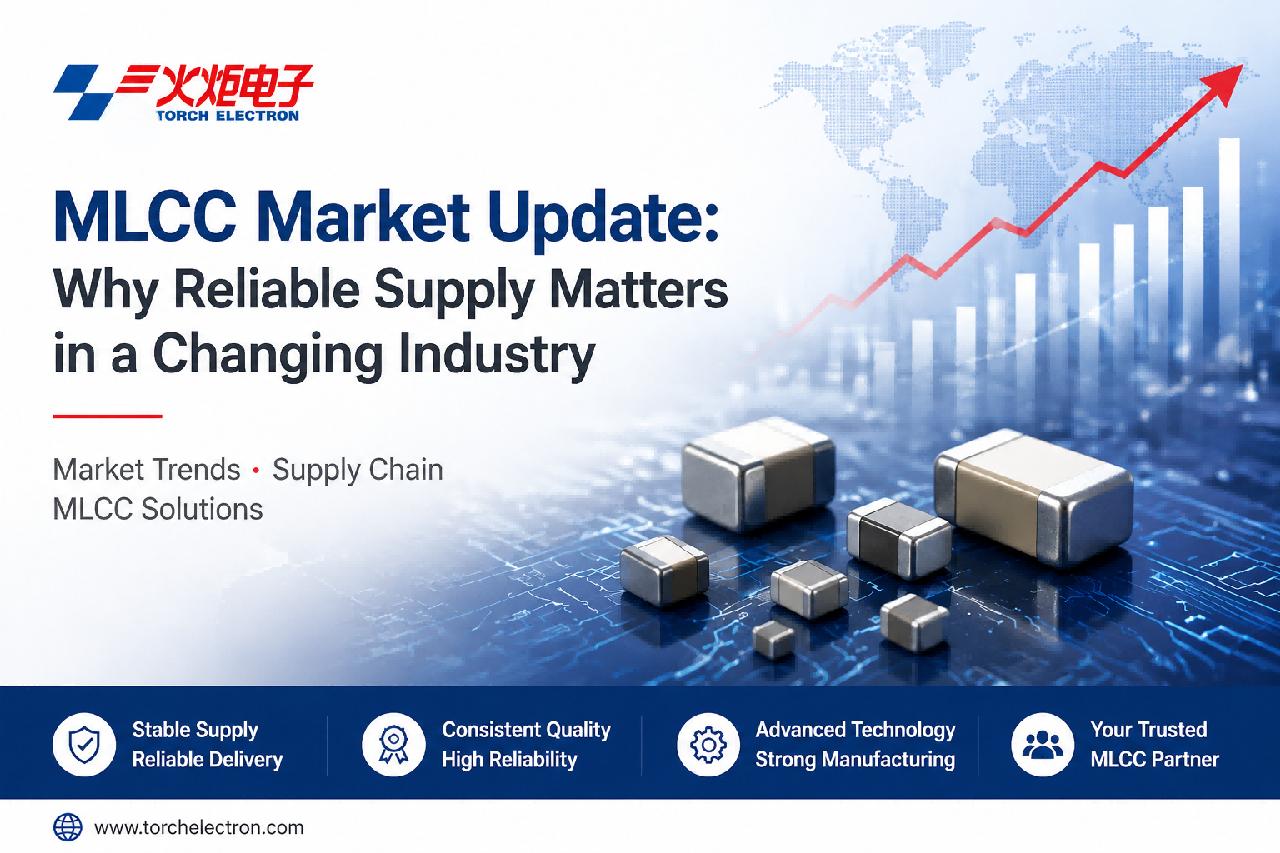
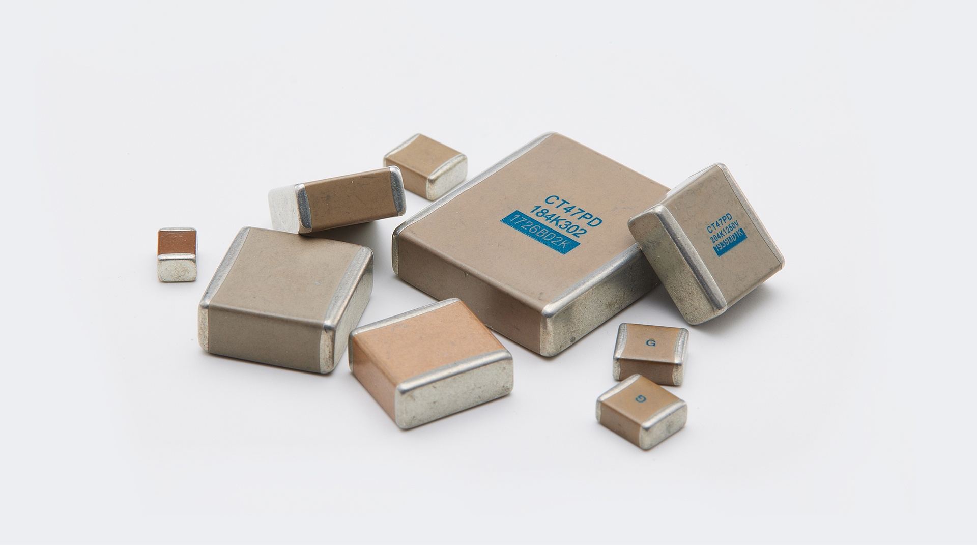
    Recently, the global MLCC market has faced challenges from rising material costs, increasing demand, and supply chain adjustments. Taiyo Yuden, one of the world's leading electronic component manufacturers, announced a new round of MLCC price adjustments, reflecting ongoing cost pressures and changing supply conditions.   As demand continues to grow in areas such as electric vehicles, artificial intelligence applications, industrial automation, and renewable energy systems, customers are paying greater attention to supplier capabilities beyond pricing. Stable production, consistent quality, and reliable delivery have become key factors when selecting an MLCC partner. In today's changing market environment, customers need more than competitive pricing. A reliable MLCC supplier should provide: · Stable manufacturing capability; · Consistent product quality; · Professional technical support; · Reliable delivery performance.   Strong manufacturing experience and technical expertise enable suppliers to better support customers’ long-term product development.   With decades of experience in capacitor manufacturing, Torch Electron has developed strong capabilities in ceramic capacitor technology, production processes, and quality management.   Torch Electron provides various MLCC solutions to meet different application requirements, including: · General-purpose MLCCs for standard electronic applications; · High Voltage MLCCs for high-voltage operating environments; · High Q MLCCs for applications requiring excellent high-frequency performance; · And other advanced ceramic capacitor solutions.    Through continuous improvement in manufacturing technology and quality systems, Torch Electron is committed to providing global customers with reliable MLCC products featuring stable performance, consistent quality, and dependable supply.   (Ceramic Capacitor Solutions Provided by Torch Electron)   Torch Electron’s MLCC solutions support various industries, including: · Automotive electronics; · Industrial control systems; · Communication equipment; · New energy applications; · High-reliability electronic devices.   By combining material expertise, manufacturing capabilities, and strict quality management, Torch Electron helps customers develop reliable electronic products and achieve long-term supply stability.   As electronic technologies continue to evolve, reliable component supply will play an increasingly important role. Torch Electron remains committed to providing high-quality MLCC solutions and supporting global customers with stable supply, consistent quality, and professional service.    
    EN SAVOIR PLUS
  • Off-Grid Photovoltaic DC Grid System
    Jul 28, 2026
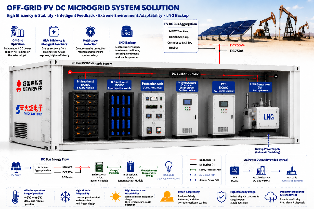
    Product Introduction This product is a hybrid energy storage system combining lithium iron phosphate batteries and supercapacitors. By integrating energy-oriented lithium iron phosphate storage with power-oriented supercapacitor technology, the system achieves coordinated scheduling through an intelligent EMS (Energy Management System). It can be directly connected to existing power supply systems without modifying the original circuits. By combining instant power buffering capability with long-duration energy storage, the system provides reliable, efficient, and green energy storage solutions for various application scenarios. It also supports both AC and DC coupling connection methods.     Outstanding Supercapacitor Performance Supercapacitors feature an extremely long charge and discharge cycle life, with more than 1 million cycles, far exceeding traditional energy storage batteries. They can continuously and reliably handle frequent high-power charging and discharging demands in high-impact load scenarios, significantly reducing equipment degradation and replacement costs. Meanwhile, supercapacitors can efficiently absorb instantaneous power fluctuations and provide power support, reducing the required capacity and quantity of lithium iron phosphate batteries. This helps lower both initial investment costs and long-term operation and maintenance expenses.   Stable and Reliable Power Supply With millisecond-level response capability, supercapacitors can quickly buffer sudden power fluctuations, effectively preventing voltage fluctuations and current surges. This helps avoid equipment shutdowns and ensures continuous and stable power supply.   Flexible Expansion and Easy Integration The system can be directly connected in parallel with existing power supply systems without modifying the original circuits, resulting in shorter upgrade cycles and lower implementation costs. It also supports flexible expansion through multiple units, making it suitable for both existing system upgrades and new projects with strong adaptability.   Safe and Compliant The system adopts an explosion-proof design with multiple safety protection mechanisms, making it suitable for special operating environments such as flammable and explosive conditions. It fully complies with industry safety and environmental protection standards, ensuring safe and reliable operation.   Energy Saving and Consumption Reduction The system can efficiently recover unused energy such as potential energy and braking energy in application scenarios. It helps smooth power fluctuations, reduce fuel consumption and carbon emissions, support green operations, and lower overall operating costs.   Drilling Platform Application During the drilling platform operation cycle, when electricity demand is relatively low in the early stage, the utilization of lithium battery energy storage units can be reduced to lower operating costs. As power demand increases in later stages, the system can flexibly adjust lithium battery storage capacity according to actual load requirements. While solving power supply challenges in drilling platform applications, the system significantly reduces energy storage investment costs and improves overall reliability through the long lifespan and enhanced safety of supercapacitors.  
    EN SAVOIR PLUS
  • Microwave Ceramic Chip Capacitors: Supporting the Development of High-Frequency Electronic Systems
    Jul 22, 2026
    The rapid development of wireless communication, radar systems, and advanced electronic equipment is driving increasing demand for high-performance RF and microwave components. In high-frequency applications, electronic components need to provide stable performance, reliability, and efficient signal transmission to support increasingly complex system requirements.无线通信、雷达系统和先进电子设备的快速发展推动了对高性能射频和微波组件需求的不断增长。在高频应用中,电子元件需要提供稳定的性能、可靠性和高效的信号传输,以支持日益复杂的系统需求。     Microwave Ceramic Chip Capacitors play an important role in modern high-frequency circuits. With excellent microwave characteristics and reliable electrical performance, these components are widely used in microwave integrated circuits (MICs), RF systems, and other applications requiring high-frequency stability.微波陶瓷芯片电容在现代高频电路中扮演着重要角色。凭借优异的微波特性和可靠的电气性能,这些元件广泛应用于微波集成电路(MIC)、射频系统及其他需要高频稳定性的应用。 As electronic systems continue to evolve toward higher integration and smaller form factors, the importance of reliable high-frequency passive components continues to grow. Microwave ceramic chip capacitors support critical circuit functions such as DC blocking, RF bypass, source bypass, and impedance matching, helping engineers achieve stable and efficient circuit designs.随着电子系统不断向更高集成度和更小的形态设计发展,可靠的高频无源元件的重要性也在不断提升。微波陶瓷芯片电容支持直流阻断、射频旁路、源旁路和阻抗匹配等关键电路功能,帮助工程师实现稳定高效的电路设计。   With advantages including compact structure, reliable performance, and suitability for advanced electronic assembly, microwave ceramic chip capacitors from Aurora Technologies support applications across microwave integrated circuits, RF systems, and other high-frequency electronic fields.凭借结构紧凑、性能可靠及适合先进电子组装等优势,Aurora Technologies的微波陶瓷芯片电容支持微波集成电路、射频系统及其他高频电子领域的应用。   As communication technologies, intelligent systems, and advanced electronic applications continue to develop, the demand for reliable microwave components will continue to increase. Looking ahead, Torch Electron believes that continued investment in core electronic components such as microwave ceramic chip capacitors will be an important driver of technological innovation, competitiveness, and long-term growth.随着通信技术、智能系统和先进电子应用的不断发展,对可靠微波元件的需求将持续增长。展望未来,Torch Electron认为,持续投资于微波陶瓷芯片电容器等核心电子元件将成为技术创新、竞争力和长期增长的重要驱动力。     Through continuous development in electronic component technologies, Torch Electron remains committed to providing high-performance solutions and supporting customers in the evolving global electronics market.通过电子元件技术的持续发展,Torch Electron始终致力于提供高性能解决方案,支持不断发展的全球电子市场中的客户。    
    EN SAVOIR PLUS
  • Ceramic Capacitors: The Complete Guide to Selection, Applications, and Troubleshooting
    Jul 08, 2026
    Ceramic Capacitors: The Complete Guide to Selection, Applications, and Troubleshooting Ceramic capacitors are among the most widely used passive components in modern electronics. From consumer gadgets to industrial power systems, their small size, low cost, and reliable performance make them indispensable. Yet many engineers and procurement specialists encounter confusion when selecting the right ceramic capacitor for their specific application. This comprehensive guide covers everything you need to know — from dielectric classifications and voltage derating to failure analysis and sourcing strategies. What Is a Ceramic Capacitor? A ceramic capacitor uses a ceramic material as its dielectric. The ceramic dielectric is sandwiched between two conductive electrodes (typically silver, nickel, or copper) to form a compact capacitor structure. The entire assembly is encapsulated in a protective coating or epoxy resin. The dielectric constant (K) of the ceramic material determines the capacitor's capacitance density — higher K values allow more capacitance in a smaller physical package, but often at the cost of stability and lower voltage handling. Types of Ceramic Capacitors 1. Multilayer Ceramic Capacitor (MLCC) MLCCs are the most common type today. They consist of multiple alternating layers of ceramic dielectric and metal electrodes stacked together. This construction achieves high capacitance values in extremely compact surface-mount packages. Typical applications: Smartphones, laptops, power supplies, automotive electronics, RF circuits. Advantages: Small footprint, high capacitance per volume, excellent high-frequency performance, lead-free compatible. 2. Disc Ceramic Capacitors Disc capacitors use a single ceramic disc as the dielectric with electrodes on both sides. They are typically through-hole components and come in two main subclasses: ceramic disc capacitors for general-purpose applications and high-voltage ceramic disc capacitors for power systems. Typical applications: Power supplies, snubber circuits, EMI suppression, high-voltage coupling. Advantages: Higher voltage ratings, robust mechanical structure, easy manual assembly. Dielectric Classes: Class 1 vs Class 2 Understanding dielectric classes is crucial for proper selection. Class 1 Dielectrics (C0G / NP0) Class 1 ceramic capacitors use low-K dielectrics like C0G (also known as NP0). They offer exceptional stability:- Capacitance change is < ±0.3% over a temperature range of -55°C to +125°C- Virtually no voltage or aging dependence- Very low dissipation factor (high Q) Best for: Timing circuits, filters, oscillators, precision analog circuits. Class 2 Dielectrics (X7R, X5R, Y5V, Z5U) Class 2 capacitors use high-K ferroelectric ceramics. They offer higher capacitance density but with trade-offs:- X7R: ±15% change over -55°C to +125°C — good stability for a Class 2- X5R: ±15% change over -55°C to +85°C — popular for consumer electronics- Y5V: +22%/-82% over -30°C to +85°C — high capacitance but poor stability- Z5U: +22%/-56% over +10°C to +85°C — worst stability, lowest cost Best for: Bypass, decoupling, bulk energy storage, power supply filtering. The Critical Factor: DC Bias Effect One of the most overlooked aspects of MLCC selection is the DC bias characteristic. Class 2 dielectrics (X7R, X5R) exhibit a significant drop in effective capacitance when a DC voltage is applied. For example, a 10 µF X5R MLCC rated at 25V may provide only 3–4 µF at its rated voltage. This phenomenon occurs because the applied DC field reduces the dielectric constant of the ferroelectric ceramic material. Practical rule: Derate Class 2 MLCCs by 50–60% in capacitance terms under operating voltage. Alternatively, switch to a higher voltage rating (e.g., use a 50V rated part for a 12V rail) to preserve effective capacitance. Common Failure Modes and How to Avoid Them 1. Mechanical Cracking MLCCs are susceptible to mechanical stress from PCB flexure during assembly or thermal cycling. Prevention: Use flexible termination MLCCs, optimize board layout to minimize bending near capacitors, and control reflow profiles. 2. Thermal Stress Rapid temperature changes during soldering can induce microcracks. Prevention: Follow manufacturer-recommended reflow profiles. Preheat the board gradually and avoid rapid cooling. 3. Voltage Overstress Applying voltage beyond the rated value can cause dielectric breakdown, especially in high-K ceramics. Prevention: Always apply a 20–50% voltage derating margin. For critical applications, use 2x rated voltage as a safety margin. 4. Aging Class 2 capacitors exhibit capacitance loss over time due to domain relaxation in the ferroelectric material. Typical aging rates are 1–5% per decade hour. Prevention: Account for aging in your design margin. Re-aging can be performed by heating above the Curie point, but this is rarely practical in-field. How to Select the Right Ceramic Capacitor Follow this step-by-step decision framework: Determine required capacitance and voltage — Start with the nominal value, then add derating margins. Choose dielectric class — Class 1 (C0G) for precision/stability, Class 2 (X7R/X5R) for general-purpose decoupling. Select package size — Surface-mount MLCC for automated assembly, disc ceramic for high voltage or prototyping. Check DC bias effect — For Class 2 MLCCs, verify effective capacitance at your operating voltage using manufacturer charts. Consider temperature range — Match the dielectric temperature characteristic to your operating environment. Verify AC performance — For high-frequency or high-ripple applications, check ESR, ESL, and self-resonant frequency. Conclusion Ceramic capacitors remain a cornerstone of electronic design, but their proper selection requires understanding beyond simple capacitance and voltage ratings. By accounting for dielectric class, DC bias effects, aging, and mechanical reliability, engineers can avoid costly redesigns and field failures. Whether you are designing a precision timing circuit or a high-density power supply, choosing the right ceramic capacitor from a reliable manufacturer is the first step toward a robust and long-lasting product.
    EN SAVOIR PLUS
  • Comment les composants électroniques alimentent les systèmes d'intelligence artificielle
    Jan 05, 2026
    Le rôle des composants électroniques dans les systèmes d'intelligence artificielleL’intelligence artificielle (IA) est souvent perçue comme une révolution logicielle pilotée par des algorithmes et des données. En réalité, tout système intelligent repose sur une infrastructure matérielle solide. Des centres de données aux périphériquesEn définitive, les performances, la stabilité et l'efficacité de l'IA dépendent de composants électroniques de haute qualité.Chez Torch Electron, une expertise de longue date dans les composants électroniques offre une vision claire de la manière dont le matériel soutient l'évolution de l'intelligence artificielle. Condensateurs dans les systèmes d'IALes condensateurs sont essentiels pour stabilité de l'alimentation et la gestion de l'énergie dans le matériel d'IA. IA haute performance Les processeurs et les accélérateurs fonctionnent sous des charges très dynamiques, nécessitant une régulation de tension fiable et une suppression du bruit.Dans les systèmes d'IA, les condensateurs sont largement utilisés pour le filtrage de l'alimentation, le découplage et la mise en mémoire tampon de l'énergie, contribuant ainsi à garantir un fonctionnement stable et une fiabilité accrue du système. Les circuits intégrés au cœur du calcul IALes circuits intégrés (CI) constituent l'épine dorsale informatique de l'intelligence artificielle. Les processeurs (CPU), les processeurs graphiques (GPU), les accélérateurs d'IA et les solutions système sur puce exécutent des algorithmes complexes et traitent des données à grande échelle.Les progrès réalisés dans la conception des circuits intégrés permettent une densité de calcul plus élevée, une meilleure efficacité énergétique et un déploiement évolutif de l'IA, du cloud à la périphérie. Dispositifs logiques permettant des parcours de décision intelligentsLes dispositifs logiques prennent en charge la logique de contrôle, le routage des données et la coordination en temps réel au sein des systèmes d'IA. Ils garantissent une communication efficace entre les processeurs, la mémoire, les capteurs et les modules périphériques, permettant ainsi des architectures matérielles d'IA flexibles et réactives. Circuits en couches minces pour l'électronique IA haute densitéLes circuits en couches minces offrent une haute précision, une taille compacte et une grande stabilité thermique, ce qui les rend adaptés à l'électronique d'IA avancée. Ils sont couramment utilisés dans le traitement du signal haute fréquence, les modules d'IA miniaturisés et les applications exigeant une fiabilité à long terme. Le matériel comme fondement de l'innovation en IAÀ mesure que l'intelligence artificielle évolue du cloud computing vers des systèmes distribués, temps réel et cognitifs, l'importance de composants électroniques de haute qualité devient de plus en plus évidente. Condensateurs, résistances, circuits intégrés, dispositifs logiques et circuits en couches minces fiables constituent l'infrastructure invisible mais essentielle de toute application intelligente.En combinant une expertise pointue dans les composants électroniques avec des investissements novateurs dans l'intelligence artificielle, Torch Electron s'engage à soutenir la prochaine génération de systèmes intelligents—faire le lien entre l’excellence matérielle et l’innovation émergente en IA.
    EN SAVOIR PLUS
  • Pourquoi les condensateurs à film deviennent un moteur de croissance stratégique pour Torch Electron
    Dec 29, 2025
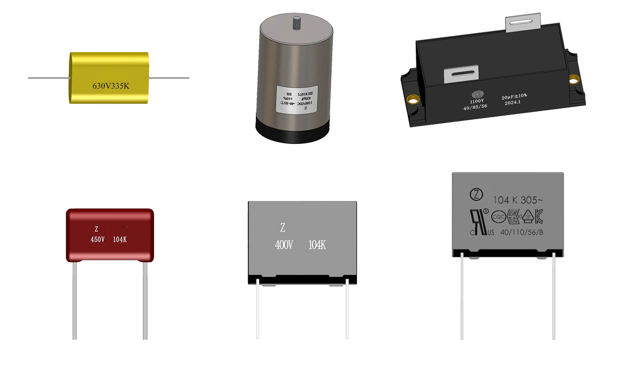
    (Condensateurs à film permettant un fonctionnement stable dans les systèmes d'énergie éolienne)Les condensateurs à film jouent un rôle essentiel dans les systèmes électroniques et électriques modernes, garantissant un fonctionnement stable et efficace dans les domaines des énergies nouvelles, de l'automatisation industrielle, du stockage d'énergie et de l'électronique automobile. Leur stabilité électrique, leur longue durée de vie et leur résistance aux conditions environnementales difficiles les rendent indispensables dans les applications à haute fiabilité. Avec l'accélération de l'électrification mondiale et de la transition énergétique, la demande en condensateurs à film haute performance ne cesse de croître. Parallèlement, la localisation des chaînes d'approvisionnement et l'intégration verticale prennent une importance croissante, notamment pour les composants électroniques essentiels présentant des barrières techniques élevées.(Campus de fabrication de Torch Electron)Torch Electron a identifié les condensateurs à film comme un axe stratégique au sein de son portefeuille de composants. En investissant dans la science des matériaux, l'ingénierie de la fiabilité et les procédés de fabrication avancés, l'entreprise se dote d'une base plus robuste et évolutive pour soutenir sa croissance à long terme.(Solutions de condensateurs à film haute fiabilité)L'intégration de Zhongxing Electronics renforce encore cette stratégie. Forte de près de trente ans d'expérience spécialisée et de ses capacités internes de fabrication de films métallisés, Zhongxing Electronics permet à Torch Electron d'innover plus rapidement, de garantir la stabilité de son approvisionnement et de répondre aux exigences spécifiques de ses clients sur les marchés mondiaux.(Torch Electron et Zhongxing Electronics – intégration stratégique)Pour l'avenir, Torche Électron elle estime que des investissements soutenus dans des composants essentiels tels que les condensateurs à film seront un moteur clé de la compétitivité, de la création de valeur et de la croissance à long terme.
    EN SAVOIR PLUS
  • Comment les normes IATF 16949 et AEC-Q définissent-elles la qualité des composants électroniques automobiles ?
    Aug 13, 2025
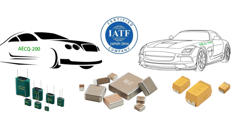
    Dans l'industrie de l'électronique automobile, qualité et fiabilité sont essentiels à la sécurité, aux performances et à la durabilité à long terme. Les fabricants et fournisseurs de composants essentiels tels que MLCC automobiles (Condensateurs céramiques multicouches)Les condensateurs au tantale et les supercondensateurs doivent répondre à des normes internationales strictes. Parmi les plus reconnues figurent les normes IATF 16949 et AEC-Q, qui définissent la fabrication des produits et leur qualification pour une utilisation dans les véhicules. Qu'est-ce que la norme IATF 16949 ? IATF 16949 Il s'agit d'une norme mondiale de gestion de la qualité automobile, élaborée par l'International Automotive Task Force (IATF) en collaboration avec l'ISO. Elle combine les exigences générales de la norme ISO 9001 avec des mesures de qualité spécifiques au secteur automobile. Pour les fournisseurs de composants électroniques de qualité automobile — de MLCC automobiles dans les unités de contrôle du moteur pour Condensateurs au tantale Dans les systèmes d'infodivertissement, la certification IATF 16949 démontre une capacité constante à répondre aux exigences des clients, à prévenir les défauts et à minimiser les variations de fabrication. Elle garantit que les processus de production des condensateurs et autres composants sont contrôlés, efficaces et fiables. Qu'est-ce que l'AEC-Q? AEC-Q Les normes, créées par l'Automotive Electronics Council (AEC), définissent les exigences de test de fiabilité des composants électroniques automobiles. Contrairement à la norme IATF 16949, axée sur les processus de fabrication, l'AEC-Q se concentre sur la qualification des composants. Par exemple: AEC-Q200 s'applique aux composants passifs tels que les composants automobiles MLCC, condensateurs au tantale, et supercondensateurs, vérifiant leur capacité à supporter les cycles de température, l'humidité, les vibrations et les contraintes électriques. AEC-Q100 s'applique aux semi-conducteurs, garantissant qu'ils fonctionnent de manière fiable dans des environnements automobiles exigeants. Lorsqu'un composant répond aux exigences AEC-Q, il a été testé pour résister aux dures réalités de l'environnement automobile, des températures extrêmes dans un compartiment moteur aux charges électriques élevées dans un groupe motopropulseur de véhicule électrique. La différence entre IATF 16949 et AEC-Q Bien que tous deux soient essentiels à la chaîne d’approvisionnement en électronique automobile, ils servent des objectifs différents : IATF 16949 est une certification basée sur les processus qui garantit qu'une entreprise peut fabriquer de manière constante des condensateurs et d'autres composants de haute qualité. AEC-Q est une qualification au niveau du produit qui garantit que ces condensateurs et composants peuvent survivre aux conditions automobiles réelles. En termes simples, la norme IATF 16949 garantit que votre usine peut produire d'excellents MLCC automobiles, condensateurs au tantale, et supercondensateurs à chaque fois, tandis que l'AEC-Q garantit que ces composants peuvent fonctionner de manière fiable dans les véhicules réels. Objectif principal de l'IATF 16949 et de l'AEC-Q L’objectif ultime des deux normes est de garantir que les composants automobiles sont sûrs, fiables et répondent aux attentes des clients. IATF 16949 se concentre sur l’amélioration continue des processus de fabrication, la prévention des défauts et l’efficacité de la chaîne d’approvisionnement automobile mondiale. AEC-Q assure à chaque personne qualifiée MLCC automobile, condensateur au tantale, ou supercondensateur peut fonctionner de manière fiable pendant toute la durée de vie du véhicule, même dans des conditions environnementales et électriques extrêmes. Pour les fournisseurs mondiaux d'électronique automobile comme Torche électroniqueLa conformité aux normes IATF 16949 et AEC-Q n'est pas seulement une certification : c'est un engagement à fournir des services fiables. MLCC automobiles, condensateurs au tantale, et supercondensateurs qui répondent aux normes automobiles les plus élevées au monde.
    EN SAVOIR PLUS
  • Condensateurs MLCC et condensateurs à film&nbsp;: différences clés pour votre conception
    Jun 24, 2025
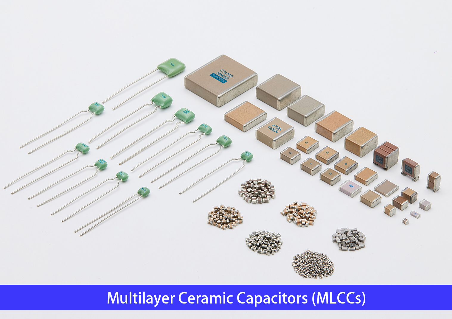
    Dans le monde des circuits électroniques, les condensateurs sont des composants fondamentaux indispensables. Parmi les nombreux types de condensateurs, notamment les condensateurs céramiques, électrolytiques, à film, à papier, à mica, les supercondensateurs et les condensateurs à glaçure de verre, Condensateurs céramiques multicouches (MLCC) et Condensateurs à film Ils se distinguent par leurs caractéristiques uniques et leur large utilisation dans différents domaines. Comprendre les principales différences entre les MLCC et les condensateurs à film est essentiel pour permettre aux ingénieurs de faire des choix de conception optimaux. La différence la plus évidente réside dans leur apparence physique. Mais en quoi les MLCC et les condensateurs à film diffèrent-ils en termes de conception ? Cet article les compare en termes de dimensions, de matériaux, de performances et d'applications afin de mettre en évidence leurs différences et les tendances futures.   1. Composition du matériau MLCC : utilisent des matériaux céramiques comme le titanate de baryum (BaTiO₃) comme diélectrique. Ces céramiques offrent des constantes diélectriques élevées, permettant d'obtenir des valeurs de capacité relativement élevées dans de petits volumes physiques. Condensateurs à film : ils utilisent des films plastiques tels que le polypropylène bi-orienté (BOPP) ou le polyimide (PI) comme diélectrique. Les électrodes sont formées à la surface du film par métallisation (dépôt de métal en phase vapeur). 2. Taille et facteur de forme MLCC : Ils présentent un avantage considérable en termes de miniaturisation. Les boîtiers les plus courants vont du minuscule 01005 (0,25 mm x 0,125 mm) au 2220 et au-delà. Ils sont donc idéaux pour les circuits imprimés haute densité des appareils compacts comme les smartphones et les tablettes. Condensateurs à film : En raison de leur procédé de fabrication et de leur structure, ils sont généralement plus grands. Obtenir des condensateurs MLCC de taille micrométrique est un défi. Cependant, leur taille est moins critique dans les applications où les performances l'emportent sur les besoins de miniaturisation, comme dans les équipements d'électronique de puissance. 3. Domaines d'application Les MLCC sont excellents dans les applications exigeant de bonnes caractéristiques haute fréquence. On les retrouve couramment dans les circuits RF, les circuits numériques à haut débit, le traitement du signal et le filtrage de l'alimentation des appareils électroniques grand public comme les téléphones et les ordinateurs. Condensateurs à film : Ils sont particulièrement adaptés aux applications haute tension et haute puissance grâce à leur tension nominale élevée, leur faible facteur de dissipation (pertes) et leur capacité d'auto-régénération. Leurs applications typiques incluent les onduleurs pour véhicules à énergie nouvelle (VEN), les systèmes de compensation de puissance réactive dans les réseaux électriques et les réseaux de croisement des équipements audio haute fidélité.   4. Performances : avantages et inconvénients   MLCC : Avantages : Très petite taille, faible coût, aptitude à la production de masse, bonne stabilité de température (pour certains types comme X7R, C0G/NP0), comme le condensateur à puce céramique multicouche CMS série Torch CC41. Inconvénients : Des valeurs de capacité plus élevées nécessitent des dimensions physiques nettement supérieures. Sujet aux défaillances thermiques sous des courants d'ondulation élevés. Sensible aux microfissures (fractures de contrainte mécanique), ce qui affecte la fiabilité et la durée de vie. Les effets piézoélectriques peuvent provoquer un bruit audible (microphonie acoustique). Condensateurs à film : Avantages : Haute précision, excellente stabilité à long terme, très faibles pertes (Q élevé), capacité à supporter des tensions élevées, capacité d'auto-guérison inhérente. Inconvénients : Processus de fabrication plus complexe entraînant des coûts plus élevés. Difficulté à obtenir de très petites tailles. Terrain d'entente : Malgré leurs différences, les MLCC et les condensateurs à film partagent la fonction principale des condensateurs : bloquer le courant continu tout en laissant passer le courant alternatif. Ils stockent et libèrent l'énergie électrique, permettant ainsi des fonctions critiques des circuits comme le filtrage, le couplage, le découplage et la résonance. Comment choisir ? Points clés pour les designers Fréquence : Pour les circuits haute fréquence, privilégiez les condensateurs MLCC. Pour les fréquences plus basses, privilégiez les condensateurs à film. Précision et stabilité : Lorsque la précision et la stabilité à long terme sont essentielles, les condensateurs à film sont supérieurs. Si la sensibilité au coût l'emporte sur la nécessité d'une précision extrême, les condensateurs MLCC offrent un meilleur rapport qualité-prix. Tension : Dans les environnements à haute tension, la haute tension nominale des condensateurs à film constitue un avantage majeur. Contraintes d'espace : dans les conceptions miniaturisées à espace limité, la petite taille des MLCC est primordiale. Coût : les MLCC présentent généralement un avantage de coût significatif, en particulier dans les applications à volume élevé. Conclusion Les MLCC et les condensateurs à film présentent des différences significatives en termes de matériaux, de taille, de performances et de domaines d'application principaux, chacun présentant des avantages et des limites spécifiques. Lors de la conception des circuits, les ingénieurs doivent évaluer soigneusement les exigences spécifiques – notamment la plage de fréquences, les niveaux de tension, les besoins de précision, les objectifs de coût et les contraintes d'espace physique – afin de comparer les compromis entre ces deux technologies de condensateurs. Faire le choix optimal garantit l'optimisation des performances du circuit, contribuant ainsi au développement continu des appareils électroniques vers des performances accrues, une plus grande miniaturisation et des coûts réduits.
    EN SAVOIR PLUS
1 2 3
Un total de 3pages

laisser un message

laisser un message
Si vous êtes intéressé par nos produits et souhaitez en savoir plus, veuillez laisser un message ici, nous vous répondrons dès que possible.
soumettre

Maison

Des produits

contact